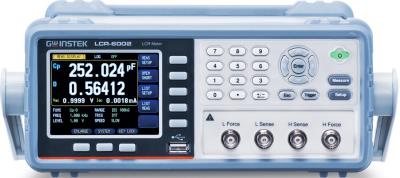
INSTEK LCR-6002 CALIBRATION and INSTEK LCR-6002 REPAIR

 
A calibration by Custom-Cal is performed by engineers with extensive OEM experience. We have the expertise and the necessary standards to perform the INSTEK LCR-6002 Calibration, onsite calibration may be available. We specialize in quick turnaround times and we can handle expedited deliveries upon request.


   INSTEK LCR-6002   Description / Specification:    
INSTEK LCR-6002 2kHz LCR Meter

The Instek LCR-6002 2kHz LCR Meter has a 3.5-inch color LCD to simultaneously display setting criteria and measurement results, it increases two additional monitoring parameters. In other words, there are four parameters, primary/secondary and two monitoring, simultaneously shown on the screen that tremendously enhances the measurement efficiency. The enlarge display mode not only emphasizes the measurement results, but also provides PASS/FAIL judgment to facilitate a rapid and convenient test result.
Specifications.

Test Frequency: 10Hz to 2kHz(±0.01%) (4 digits resolution).
Output impedance: 30Ω / 50Ω / 100Ω selectable.
Basic Accuracy: 0.05% (Slow / Med), 0.1% (Fast).
Test Speed: FAST:25ms / MED:100ms / SLOW:333ms.
Test Signal Levels.
  AC Voltage: 10.00mV to 2.00V (±10%), CV 10.00mV- to 2.00V (±6%).
  AC Current: 100.0μA to 20.00mA (±10%), CC 100.0μA to 20.00mA (±6%) (@2VMax).
  DCR: +2V, 0.066A (Max.), Output impedance fixed 30Ω.
DC Bias Internal: ±2.5V (0.5%+0.005V).
Display Range.
  R, X, |Z|: 0.00001Ω ~ 99.9999MΩ,
  G, B, |Y|: 0.01nS ~ 999.999S,
  L: 0.00001μH ~ 9999.99H,
  C: 0.00001pF ~ 9999.99mF,
  D: 0.00001 ~ 9.99999,
  Q: 0.00001 ~ 99999.9,
  θd: -179.999° ~ 179.999°,
  θr: -3.14159 ~ 3.14159,
  DCR: 0.00001Ω ~ 99.9999MΩ,
  Δ%: -99999% ~ 99999%.
Test Mode Combinations (16): Cs-Rs, Cs-D, Cp-Rp, Cp-D, Lp-Rp, Lp-Q, Ls-Rs, Ls-Q, Rs-Q, Rp-Q, R-X, Z-θr, Z-θd, Z-D, Z-Q, DCR.


Related Bench Equipment Terms and Definitions. For a complete list go to our  Terms and Definitions Page.

Channel Bandwidth
Channel Bandwidth is the bandwidth over which power is measured. This is usually the bandwidth in which almost all of the power of a signal is contained.

Jitter
Jitter in technical terms is the deviation in or displacement of some aspect of the pulses in a high-frequency digital signal. Jitter is the time variation of a periodic signal in electronics and telecommunications, often in relation to a reference clock source. Jitter may be observed in characteristics such as the frequency of successive pulses, the signal amplitude, or phase of periodic signals. Jitter is a significant, and usually undesired, factor in the design of almost all communications links (e.g., USB, PCI-e, SATA, OC-48). In clock recovery applications it is called timing jitter.

Overshoot
Overshoot is the distortion that follows a major transition; the difference between the peak power point and the pulse-top amplitude computed as a percentage of the pulse-top amplitude.

Rise Time
Rise time refers to the time required for a signal to change from a specified low value to a specified high value, usually 10 and 90 percent of pulse-top amplitude (vertical display is linear power).


Please contact us for your INSTEK LCR-6002 CALIBRATION and/or INSTEK LCR-6002 2kHz LCR Meter REPAIR

I'm interested in: 
Calibration Type (Select one):
Repair Information:
 Serial Number:

 Is there any physical damage?  
 If yes, describe:


What is the description of the problem?

How/when did the problem start?


 (*) Required Fields    For formal quote please fill in all fields.
Company:
From (Email):*
Contact Name:*
Country:*
Address 1:
Address 2:
City:
State/Territory/Province: *
Zip/Postal Code:
Phone:*

Comment: